Mechanical Design
One of the main goals of the project is to design a sample stage that can achieve micro-scale movements to bring a sample within the scanning range of the MEMS device tip. A stable mechanical design is also required to limit inherent vibrations in the system which are detrimental to the quality of images produced by the device.
Design of a viable mechanical approach mechanism was an essential limiting step for the whole project. Considerable effort was put in designing and perfecting a mechanism that fulfills the needs described above.
Since cost is one the main criteria, it important to achieve this goal by using as many generic components as possible that can be assembled together with simple fabrication processes.
Solutions using high precision steppers motors or linear actuators are very expensive and thus were ruled out. An alternative design which uses readily available parts and fundamental mechanical principles for converting rotational motion to linear motion is used.
Designs Considered
The following are mock-ups of different concepts considered for mechanical design.
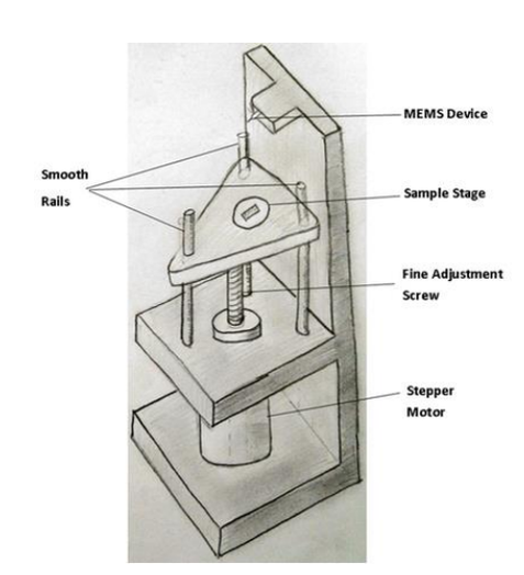
Precision-screw Based Vertical Approach
In order to achieve micro scale movements, a common solution used is a fine adjustment screw which translates rotary motion into very fine linear movements. This fine movement is achieved with an extremely fine thread that has a pitch of only a few micrometers. If the screw is driven using a stepper motor, an approach resolution of 30 microns can be achieved.
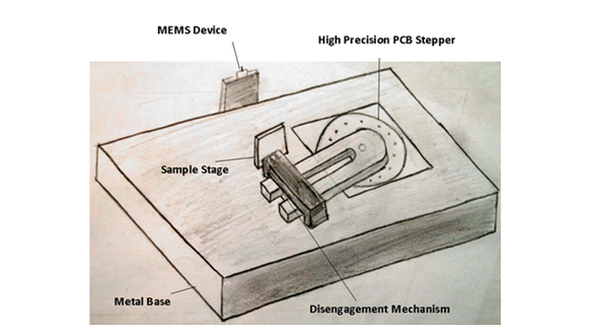
PCB Motor Based Design
Another solution considered is a relatively expensive PCB Motor that allows extremely fine movements to be achieved in the angular direction. These PCB motors are relatively new to the market. The motor has a rotor suspended in the middle of a circular array of piezoelectric crystals embedded into a PCB. A wave of impulses sequentially activate crystals causing the rotor to move in extremely fine steps. A sample stage attached to this motor can be used to approach the MEMS device with a resolution that is within our requirements.
Another solution considered is a relatively expensive PCB Motor that allows extremely fine movements to be achieved in the angular direction. These PCB motors are relatively new to the market. The motor has a rotor suspended in the middle of a circular array of piezoelectric crystals embedded into a PCB. A wave of impulses sequentially activate crystals causing the rotor to move in extremely fine steps. A sample stage attached to this motor can be used to approach the MEMS device with a resolution that is within our requirements.
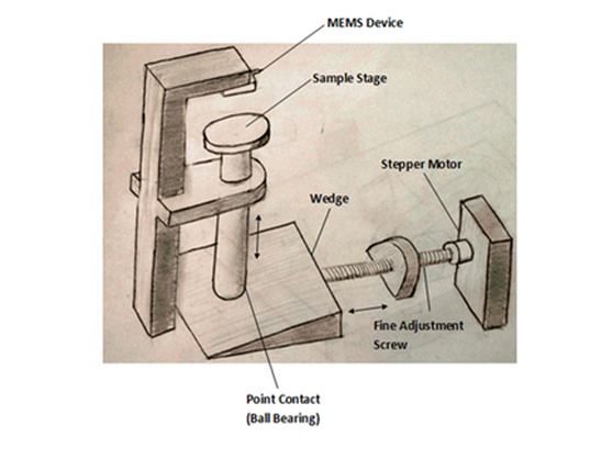
Wedge Based Design
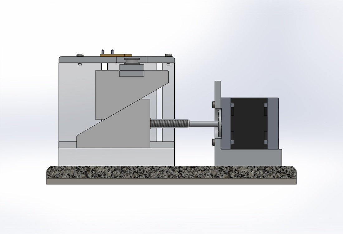
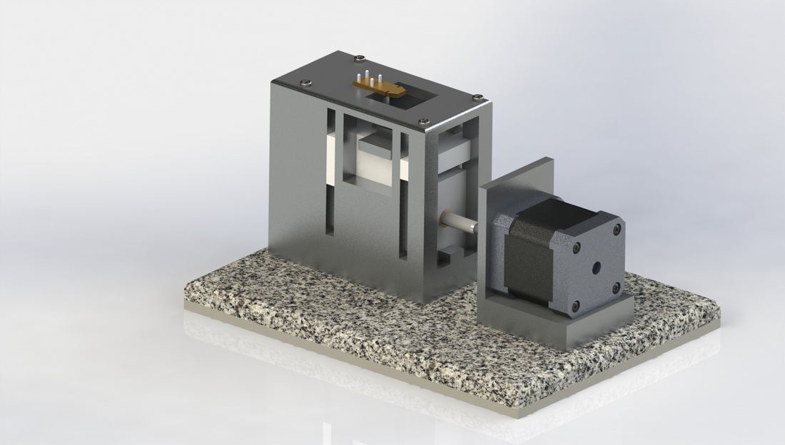
This concept, the first concept relies on a fine adjustment screw connected to a PCB motor. The difference is that the orientation of the screw is horizontal. In order to translate this horizontal motion to a vertical motion, a wedge is used which has an added advantage of further decreasing the step size due to the angle provided by it.
This concept, the first concept relies on a fine adjustment screw connected to a PCB motor. The difference is that the orientation of the screw is horizontal. In order to translate this horizontal motion to a vertical motion, a wedge is used which has an added advantage of further decreasing the step size due to the angle provided by it.
Evolution of Final Design
Even though all designs serve the requirements of the project, through extensive research it was determined that the first design is mechanically unstable, and was therefore not pursued. The third was determined to be cheaper to manufacture but the concept has never been tested in any existing AFMs and is fairly complex. The second concept is simple and uses a well-tested and well-documented mechanism but relies on a high-precision PCB motor which is fairly expensive. The team decided to pursue both concepts and select the most feasible one.
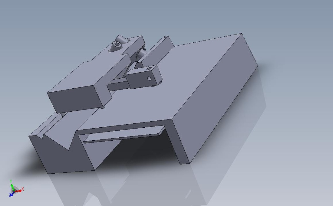
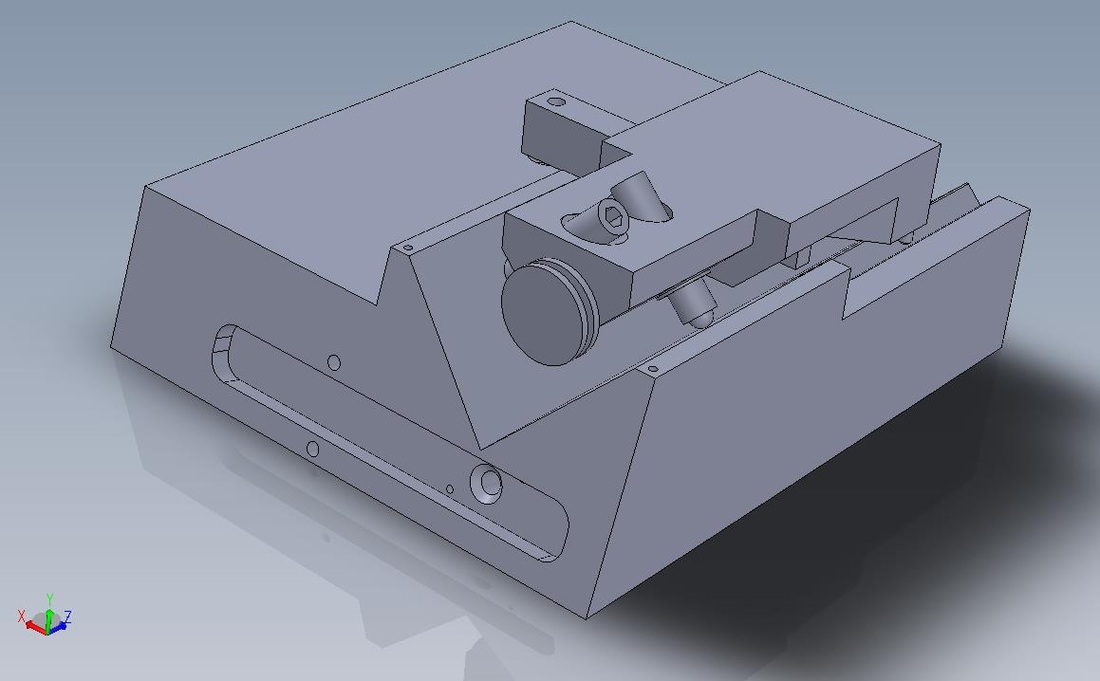
The concepts were further developed and tested in Solidworks. The following gallery shows renders of the 3d Models Developed:
Even though all designs serve the requirements of the project, through extensive research it was determined that the first design is mechanically unstable, and was therefore not pursued. The third was determined to be cheaper to manufacture but the concept has never been tested in any existing AFMs and is fairly complex. The second concept is simple and uses a well-tested and well-documented mechanism but relies on a high-precision PCB motor which is fairly expensive. The team decided to pursue both concepts and select the most feasible one.
The concepts were further developed and tested in Solidworks. The following gallery shows renders of the 3d Models Developed:
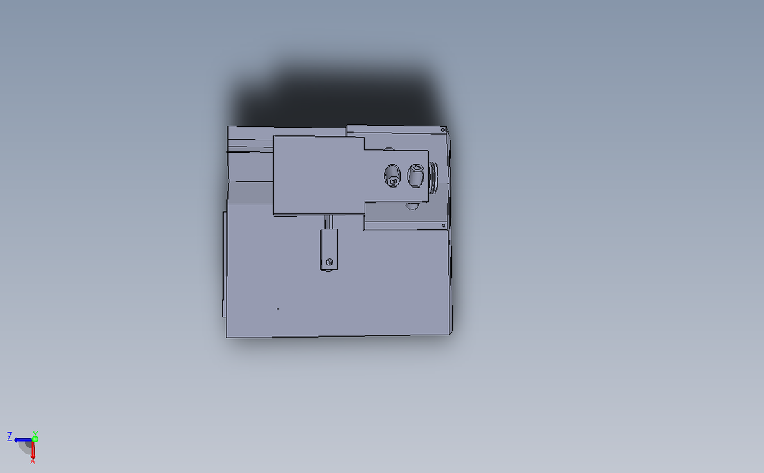
Both designs were verified to work in simulation and were then taken to a contractor in order to get them fabricated. Due the nature of materials used and uncertainty of the design being successful in physical form, it was determined that pursuing the wedge-based design is not feasible given the time available for the project. The PCB-motor design is easy to implement as most of the work is carried out by the pre-fabricated motor and the rest of the parts can easily be 3D printed. The design was therefore pursued fully and manufactured as a stage for the AFM device.
Electrical Design
The whole system has two distinct electro-mechanical subsystems i.e the stage used to engage the probe with the sample and the MEMS based AFM device itself which consists of thermal actuators and a sensing tip. The electrical design provides the following functionality to service these subsystems:
1) Interface with the MEMS Device
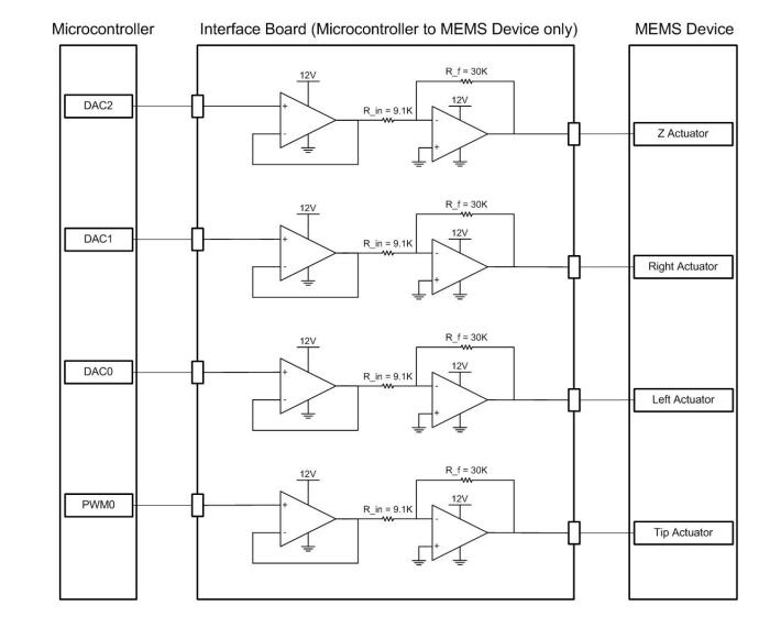
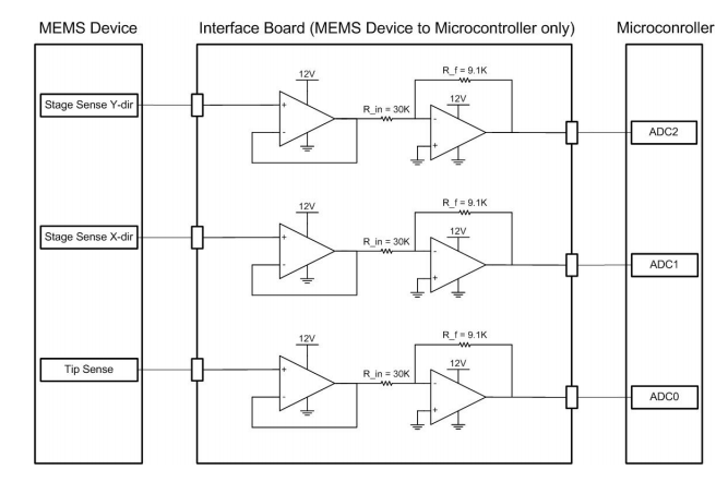
Since the device works in such a small scale, the electrical signals used to control it have to be buffered and conditioned accurately in order to excite predictably excite the system . The electrical design therefore incorporates signal conditioning circuitry to provide precise and noise-free signals to the device and help in the amplification and filtering of sensing signals such that a decent quality image can be obtained.
2) Control of Sample Stage
The electrical design also provides an interface to control the movement of the sample stage.
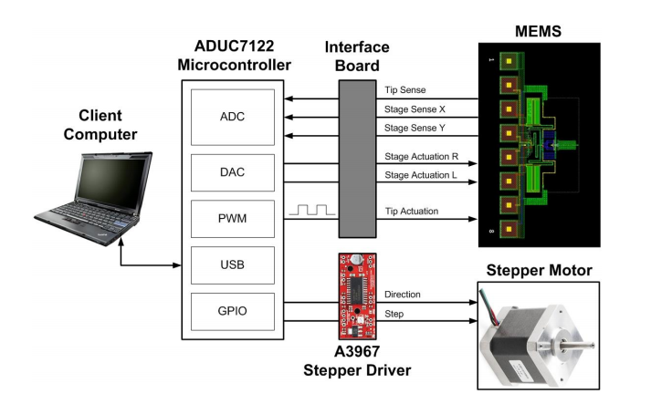
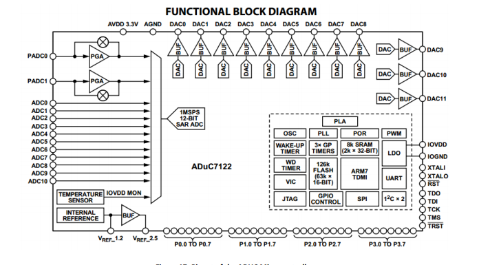
From a higher level view, the electronics are implemented around an Analog Devices ADuC7122 micro-controller. This micro-controller fits the application perfectly as it contains 12-bit DACs and ADCs which are used to drive and sense the MEMS device respectively. The micro-controller also has a serial interface which allows it to connect to a client computer in order to control the functioning of the device. The following gallery shows block diagrams for the electronics working together:
1) Interface with the MEMS Device
Since the device works in such a small scale, the electrical signals used to control it have to be buffered and conditioned accurately in order to excite predictably excite the system . The electrical design therefore incorporates signal conditioning circuitry to provide precise and noise-free signals to the device and help in the amplification and filtering of sensing signals such that a decent quality image can be obtained.
2) Control of Sample Stage
The electrical design also provides an interface to control the movement of the sample stage.
From a higher level view, the electronics are implemented around an Analog Devices ADuC7122 micro-controller. This micro-controller fits the application perfectly as it contains 12-bit DACs and ADCs which are used to drive and sense the MEMS device respectively. The micro-controller also has a serial interface which allows it to connect to a client computer in order to control the functioning of the device. The following gallery shows block diagrams for the electronics working together:
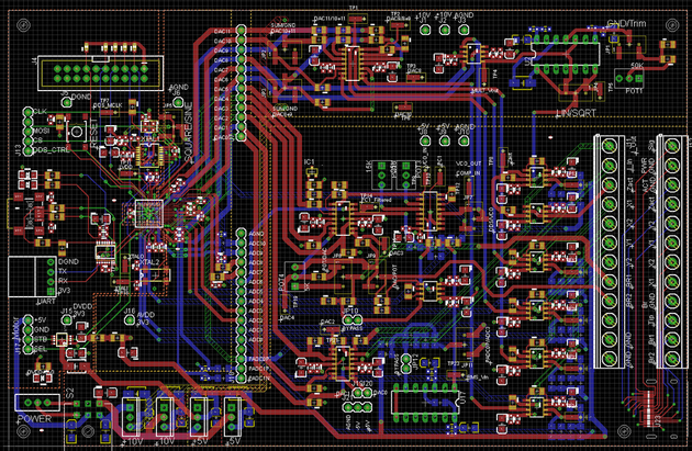
The micro-controller and the MEMS Device circuitry have been integrated and laid out on a single PCB as shown in the picture to the left. The layout was fabricated and populated and is used to interface and control the AFM for imaging.
Software Design
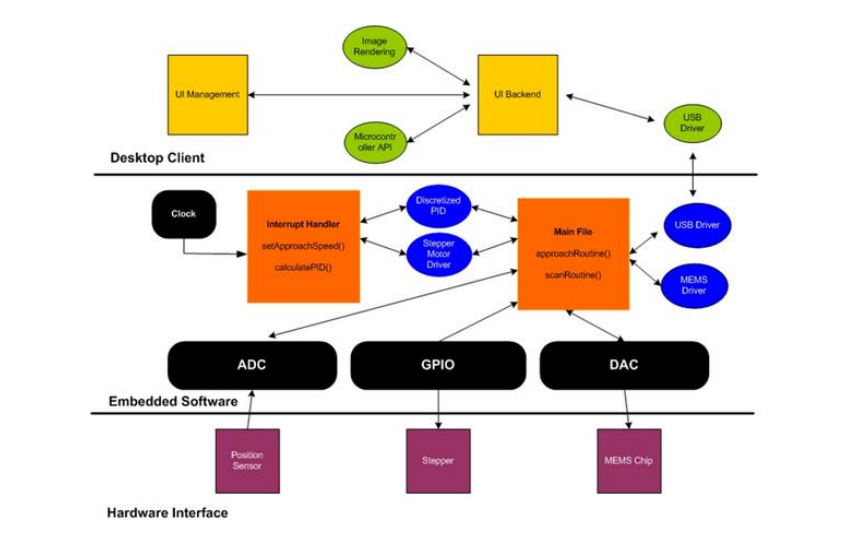
The software design for the project is split into two distinct parts. A low level software runs on the microcontroller and implements various algorithms to control the MEMS device and the approach mechanism. A higher level software implements the graphics user interface that allows the users to control various parameters for controlling the MEMS device and also renders and displays image dataded.
Embedded Software
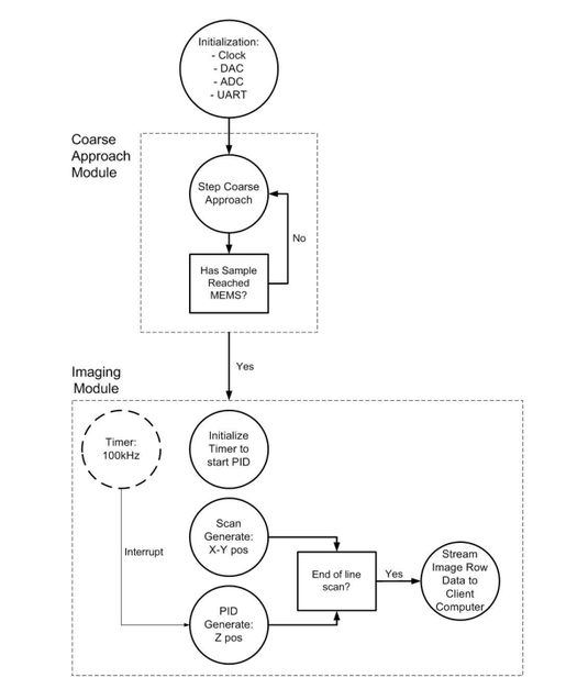
The code that runs on the microcontroller is responsible for interacting with the MEMS device, the client computer, and the coarse approach.
The coarse approach module handles driving the stepper motor one step at a time and checking to see if the sample has approached the tip. The tip is put in resonance and the stopping condition comes from sampling the voltage of the MEMS tip sense which is readable.
The imaging module contains two major components. The first component is the scan generator which is responsible for producing the X and Y Cartesian coordinates and driving the
MEMS stage such that the tip ends up at the correct points using its actuators. The second component generates a control loop required to properly engage the tip with the sample and extract the height component Z at the correct location.
The flow chart on the left provides a detailed overview of the internals of the embedded software implemented for the project.
Client Software
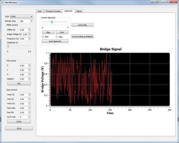
The client software is the final piece in the whole system and allows the users to conveniently use the AFM to extract images of samples. The client software has been designed to expose as much functionality as possible to the user while keeping the interface relatively simple.
The software was created using Qt which allows the same code to be ported to various platforms including Linux, Windows and Mac. It implements both a Serial Port driver which communicates with the micro-controller and also a user-interface with all features required by researchers to control the AFM and display vital data back to the user.
The pictures on the right is a screenshot of the UI designed.
The following is an overview of various components implemented in software: